
This is a very simple and easy-to-build project that provides a sensor on the pedal crank of any exercise bike and generates keyboard output triggering Google Maps Street View to advance via the up arrow key.
In my design, you pedal the crank five times, and then the Street View receives an up-arrow command that advances you to the next Street View panorama. Steering is not included, but it should be possible to easily add it via switches attached to the hand grips on your exercise bike.
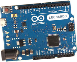 The recent release of the Arduino Leonardo allows this project to be constructed with a minimum of effort. The Arduino is a popular miniature computer capable of being programmed from your desktop or laptop, and it can run on its own after you program it and disconnect it from the PC. It has a number of input and output pins, including both digital and analog inputs. It is very popular with the DIY crowd and has been integrated into hundreds of projects. This is my first original project using the Arduino.
The Leonardo, unlike the other flavors of the Arduino (there are many variants), has a built-in keyboard and mouse emulator that allows the Arduino to mimic the behavior of a USB keyboard or mouse.
Here are the steps you will need to complete the project.
Parts List
- 1 Arduino Leonardo, $24.95. This version includes headers, which are small plastic extenders from the board allowing you make connections simply by plugging wires in the holes of the header. If you intend to solder your connections, get the “without headers” version, which is slightly cheaper. Please note the Arduino Uno model sold in Radio Shack stores is not the right one for this project and will not work. You have to have an Arduino Leonardo.
- 1 magnetic reed switch, Radio Shack part 54-630 or equivalent, $3.66
- 1 USB to micro-USB cable or adapter, Radio Shack 26-2738 or equivalent, must be long enough to reach from your exercise bike to your PC, $9.99
- 1 10K Ohm resistor, Radio Shack 271-1335 or equivalent, $5 for $1.19
- Arduino software (latest version)
- Any Google Maps Street View compatible computer (I used a MacBook Pro, but it should theoretically work on almost anything).
- Any exercise bike with about 2″ clearance between the pedal crank and the housing.
Total expense is less than $50 including shipping – less if you have parts on hand or a nearby Radio Shack or electronics store.
Building the Interface
Next, you will need to interface the Arduino with your computer. Connect the USB cable from the Arduino to your computer. On a Mac, the interface step simply involves closing the Unrecognized keyboard dialog that automatically pops up. It works “out of the box”. Detailed instructions for how to accomplish this for other computers are posted online.
Magnetic reed switch
Next, you will need to attach the magnetic reed switch to the board. The switch is “ON” when the sensor is near the included magnet. It triggers within about a quarter inch, so it’s pretty tolerant of things that don’t quite line up. Put one lead of the magnetic reed switch in the hole marked D2 and the other in +5V on the other side of the board. You will also need to put one of the 10K Ohm resistors in the same pin 2 hole and push the other end into the GND connection on the board.
That’s it for the circuit. Now download and install the Arduino software: download streetview.txt or copy this program file:
 /*
Exercise Bike Interface to Google Maps Street View
Based on Keyboard.Message Example Program.
 Sends a text string when a button is pressed.

 The circuit:
 * Magnetic reed switch attached from pin 2 to +5V
 * 10-kilohm resistor attached from pin 2 to ground

 created 24 Oct 2011
 modified 27 Mar 2012
 by Tom Igoe
 modified 24 June 2012
 by Jeff Adkins

This example code is in the public domain.

 http://www.arduino.cc/en/Tutorial/KeyboardButton
 */
 //initialization of constants

const int buttonPin = 2;          // input pin for pushbutton
int previousButtonState = HIGH;   // for checking the state of a pushButton
int counter = 0;                  // button push counter
const int crankratio =5;          // number of pedals that invokes a single "up arrow"
int debounceFlag1 = 0;            // debounce flag
int debounceFlag2 = 0;            // debounce flag
// The debounce flags are two separate magnetic field inputs taken one after the other.
// if they match, then the switch is assumed to have actually triggered.

void setup() {
  // make the pushButton pin an input:
  pinMode(buttonPin, INPUT);
  // initialize control over the keyboard:
  Keyboard.begin();
}

// Main Loop
void loop() {
  // read the pushbutton:
  int buttonState = digitalRead(buttonPin);
  // if the button state has changed,
  if ((buttonState != previousButtonState)
    // and it's currently pressed:
  && (buttonState == HIGH)) {
    // set debounceflag1 = buttonState
    debounceFlag1 = buttonState;
   // delay 3 ms and read it again
   delay (3);
   debounceFlag2 = digitalRead(buttonPin);
   // if it still reads High after 3 ms delay
   if (debounceFlag1 = debounceFlag2); {
      // increment the button counter
      counter++;
      // keyboard print test
      //Keyboard.print(counter);
      if (counter>=crankratio){
        counter = 0;
        // type out a message
        //Keyboard.print("You pressed the button ");
        //Keyboard.print(counter);
        //Keyboard.println(" times.");
        Keyboard.press(218);
        delay(100);
        Keyboard.release(218);
        delay(100);
      }
    }
    debounceFlag1 = 0;
    debounceFlag2 = 0;
  }
  // save the current button state for comparison next time:
  previousButtonState = buttonState;
}
You can either paste the code into an empty window (called a “sketch”) or open the file with the file dialog. Then press “upload.” That’s the right-hand arrow button in the sketch window.
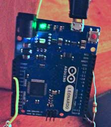
Lit LEDs mean it’s working.
You should see LED lights blinking on the Arduino for a few seconds. After a few moments, the status line at the bottom of the window should say Done uploading.
Be careful not to trigger the magnetic switch now, because your keyboard will emit up-arrows in whatever application is in the foreground.
Testing the Interface
To test your setup, open a word processor document and enter a few carriage returns. Wave the magnet near the sensor five times, and you should see the cursor move up the page one space. If that works, you are good to go.
If you want to adjust the number of cranks it takes to trigger an advance in the map, change the line that reads const int crankratio =5; // number of pedals that invokes a single "up arrow" to whatever value you want.
I am not going to go into a detailed breakdown of the software here, but here are a few things you might like to know. The ASCII code for up arrow is 218. If you have a computer that maps a different code to up arrow, that number would need to change. I have no idea if that will be required on a PC or other machine. My guess is probably not.
Also, if you find it is advancing with erratic numbers of triggers – meaning sometimes you pedal once and it advances and sometimes you pedal 3, 5, or more times – this is probably due to the switch not being debounced. When a switch is pressed, there are sometimes microsecond intervals where the signal is activated and then disconnected as the switch slowly makes contact. (Slow in the sense of high speed electronic circuitry.) This program provides a short delay for software-based debouncing and makes sure the switch is still closed after a 3 ms interval. If it doesn’t work consistently for you you could try making that “delay (3)” a little interval longer.
Using the Interface
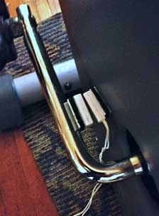
I attached the sensor to the bike’s frame with Velcro™ and the magnet to the inside of the crank arm near the pedal. You might need to make some adjustments to bring the magnet as close as possible to the sensor without running into it. My experience is that the sensor was pretty forgiving – it isn’t even lined up quite straight on mine, and it works.
Next, with the sensor in place, the software loaded (it runs automatically), and the board plugged into the computer you intend to use, set up Google Maps with Street View and activate fullscreen view.
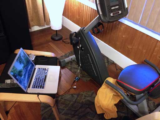
Exercise bike, Arduino interface, MacBook, and Google Maps Street View.
You can use the built-in Maps view to save where you left off if you want to keep going. It is my intention to virtually ride all the way across the country in Street View. I admit this will be much easier than actually riding across the country, but even this should provide me with a lot of exercise and some fun exploring small towns and various sights along the way in Street View. I imagine the ratio isn’t constant throughout the country (distance covered vs. number of panos taken by the Street Map van), but this is a start.
My next step is to add additional momentary pushbutton switches for “left arrow” and “right arrow” so I can steer while I ride without taking my hands off the bike. Every now and then I imagine I’ll just stop and look around at whatever is nearby.
I had a lot of fun with this project, and it is perfect for the beginner to get your feet wet with the Arduino hardware and software. If you try it, drop me a note.
Keywords: #arduino #googlestreetview #exercisebike #maclabreport
Short link: http://goo.gl/2qGHSY
searchword: bikecrosscountry
