
For years now, myself and many others have made attempts to upgrade soldered RAM on PowerPC-based Macs, without any success.
As I’ve found from my vast experience doing such upgrades on Intel machines, just swapping the chips is not all that needs to be done. The system’s BootROM also has to be modified in such a way that it actually knows the memory configuration that is installed, in lieu of having the SPD, or “Serial Presence Detect” EEPROM that is present on all removable DIMM memory modules.
On Intel systems, this was easy to figure out, as the Intel system BIOS is designed to load hard-coded entries of data in the exact same format as it would be found on the SPD EEPROM of a memory module.
On PowerPC Macs, however, they have a completely custom config entry format that describes the soldered memory configuration, as well as a lot of other configuration options of the machine, which I was finally able to figure out all thanks to @LightBulbFun‘s discovery of this “Boot Flash System Configuration Block” document he was somehow able to find (attached).
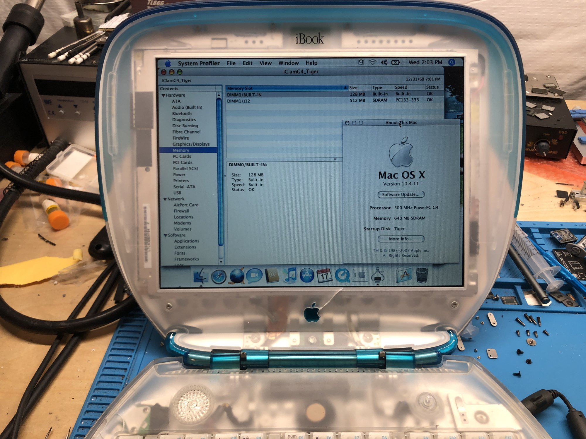
With that, I was able to edit the data appropriately to successfully upgrade the onboard RAM of a 1st gen iBook G3 Clamshell from 64MB to 128MB! Below, I will describe the exact process, which should apply to any PowerPC Mac with soldered RAM.
.
Upgrading the actual hardware
When choosing new chips to install, you must be aware of the following:
- The data width (8-bit, 16-bit, 32-bit) of the new chips must match that of the originals (this can be determined by the respective datasheets).
. - The number of required address lines on larger memory chips will likely be increased. You must make sure that the target board actually has these extra lines routed out; you can check using a multimeter in diode mode. In this example I am not actually increasing the chip density, but adding 4 extra chips omitted from the factory, though in most cases this won’t be the case.
.- In some cases, if your board doesn’t have the address lines needed for larger density chips routed, you may be able to bodge them out from another chip or location on the board using wire, though I won’t be covering this here.
.
- In some cases, if your board doesn’t have the address lines needed for larger density chips routed, you may be able to bodge them out from another chip or location on the board using wire, though I won’t be covering this here.
- You must ensure the memory config you choose is actually supported by the platform you’re working with.
. - The footprint/package of the new chips must match that of the originals (otherwise you couldn’t even solder them onto the board).
. - All installed memory chips must match in specification, though the manufacturer doesn’t matter (you can mix and match whatever chips you want as long as their specs match).
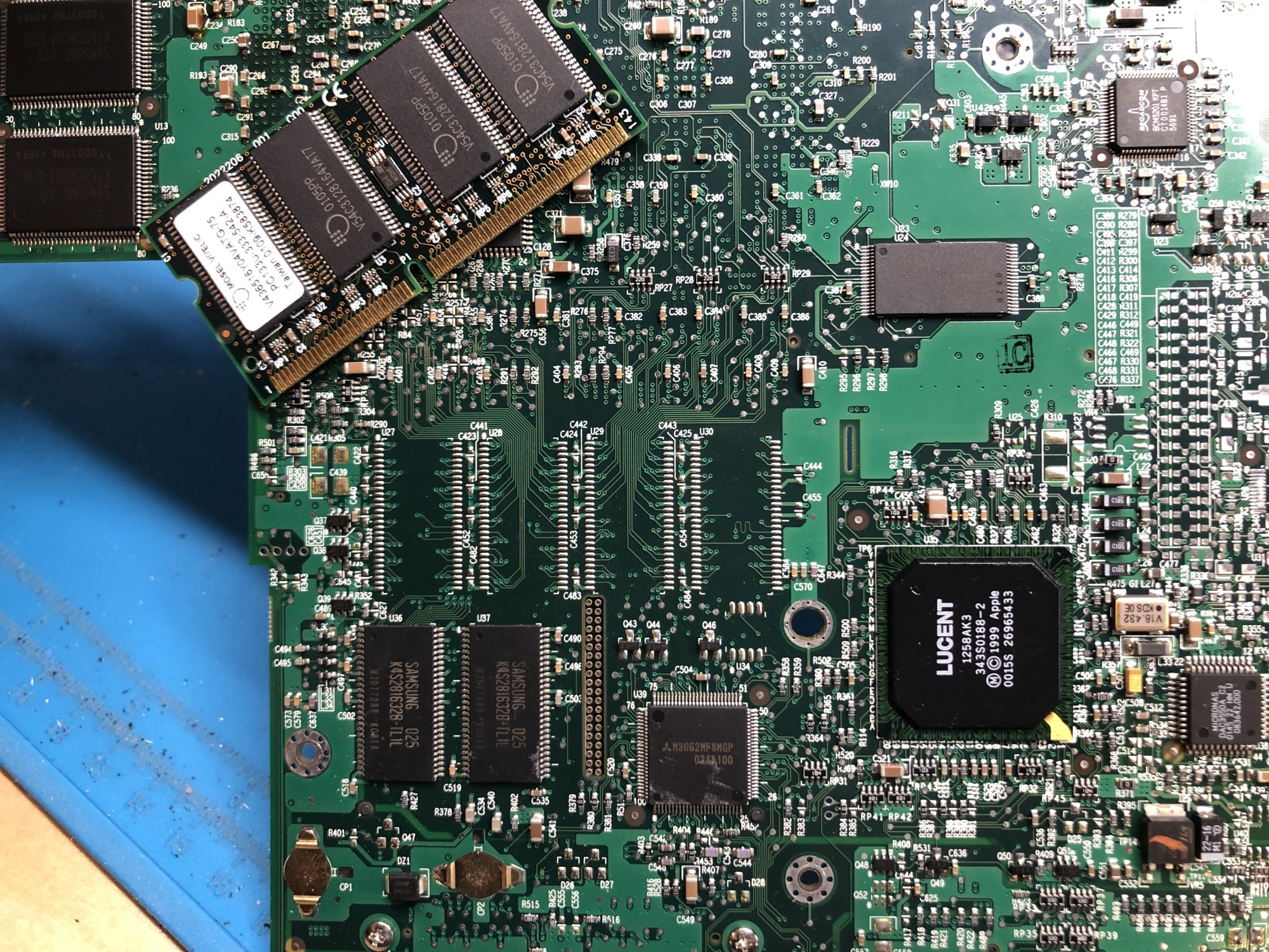
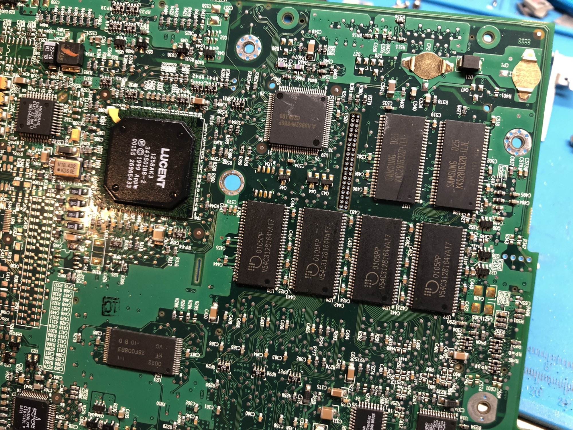
Once you have determined and obtained the desired chips, all you have to do is solder them on. In the case of the Clamshell iBook here, since I am adding an additional 4 chips, I had to add some decoupling capacitors that were also omitted. I ended up finding a PC-100 SO-DIMM module I had laying around to pull the new chips from, so I just used the capacitors from that as well.
I ended up adding 4x 128Mbit 16-bit memory chips to the original 4x 128Mbit 16-bit chips. I should note that this particular board did NOT have any extra address lines routed (only the 12 needed for 128Mbit chips), so bodging would be required to use larger density chips here.
.
.
Once you solder everything on, boot the machine as-is and make sure it works. It will not detect any more memory than it had originally at this point, but should still boot and work just fine. If it fails to boot, you have a soldering issue (or bad/incompatible chip(s)), which needs to be resolved before continuing.
.
Making the BootROM modifications
If all has gone well so far, now is the final part of the process that makes all your soldering work worth it; actually getting the machine to detect all the memory you installed.
.
Dumping EEPROM
To begin, the first thing you need to do is get a clean dump of your machine’s BootROM. There are two ways to do this; either desolder and dump your system’s EEPROM externally using an EEPROM programmer, or boot Linux on the machine and use Flashrom to dump the EEPROM. Be aware that to do this, you must ensure the machine is booted into firmware programming mode (hold power button at boot until power LED starts flashing), otherwise the EEPROM will not be exposed to the OS. The correct command to dump a BootROM with Flashrom is:
- Code:
flashrom -p internal -r backup.bin
.
Modifying content
Once you obtain a dump of your machine’s BootROM, open it in a hex editor of your choice. Following the attached document, you need to start by searching for the “signature” hex value, which is C99C. There may be multiple entries of this value, but the correct one is easy to spot, and will be right before the NVRAM section (which is denoted by “nvram” in ASCII, so it is easy to spot.)
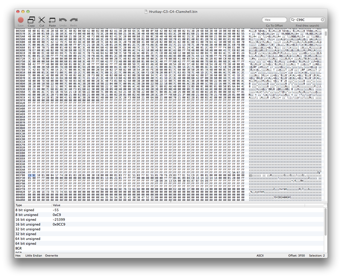
Going back to the document once again, you need to locate the memory configuration section of this block. It is located at offset 0x50, or 80 bytes from the first 0xC9 (which is considered offset 0, you can copy and paste the whole section (0x100 or 256 bytes) to a new document for easier parsing). From the datasheet for your new chips, you need to determine the following values:
- Number of row addresses
- Number of column addresses
- Number of banks on SDRAM device
You can determine each of these values from the datasheet for your new chips, which is normally laid out as shown here:
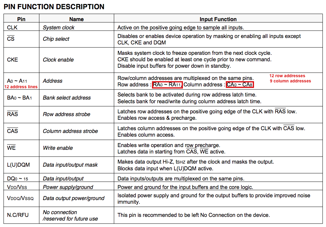
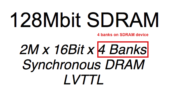
These values are just set as raw hex values, so for the 128Mbit chips here, that looks like the following:
![]()
0x0C = 12 row addresses, 0x09 = 9 column addresses, 0x04 = 4 banks on SDRAM device.
If you are adding another set of chips, like in the case of this iBook, there is one more value that needs to be updated, “Number of soldered memory controller banks”. This is just a raw hex value once again, located at offet 0x5C, and in my case I simply had to change this from 0x01 to 0x02 (to singnify the added 4 chips (or “bank”) of memory).
- Note: If you are not adding chips, this value should not be altered.
.
Updating checksum
The modification that had to be made is to update the Adler32 checksum of this section with the content of the edited data. There are many ways do do this, but I find the easiest way to be copying the data you need to calculate the checksum on into a new file, then use any tool to calculate the Adler32 checksum of that file. The layout is shown below:
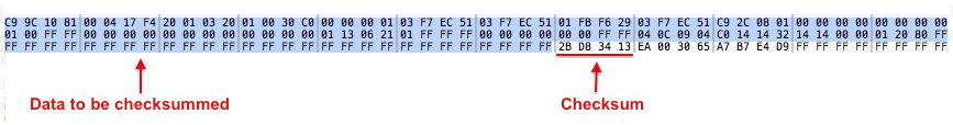
If you don’t have a local tool to calculate the checksum, you can always use this site.
.
Flashing EEPROM with modified content
With all those edits complete, you’re done! Now, all you need to do is write the modified BootROM image back onto the EEPROM. Again, this can be done externally using an EEPROM programmer, or using Flashrom under Linux with the following command:
Code:flashrom -p internal -w modified_bootrom.bin
.
- Download: Configblk_2.5.15.pdf (79 Kb, LEM Repository)
